Technical Information
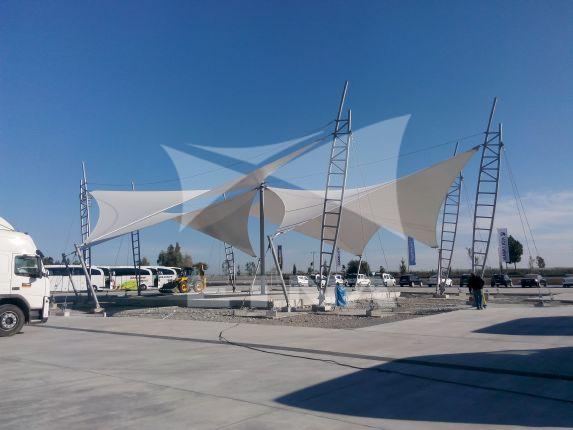
Suspended tensioning systems are curvilinear structures in which the membrane cover, which carries only a tensile force, is stretched to create a load-bearing capacity. Membrane cover systems are used as a roof element in the building thanks to their economical and impressively wide span span. These types of systems are generally used in the construction of sports facilities, stadiums/tribunes, amphitheaters, multi-purpose buildings, marketplaces, inter-building closures, parks/gardens/landscaping areas, walkways, children’s playgrounds, parking lots, warehouses and hangar buildings.
The first calculations on the stresses and deformations of suspended tension structures, shells and membranes were made by Russian engineer Vladimir Shukhov. For the 1896 Nizhny Novgorod Fair, he designed a suspended tension structure covering an area of 27,000 square meters with the function of an exhibition and pavilion. In recent years, suspended tension structures have found great popularity and have been used in many places.
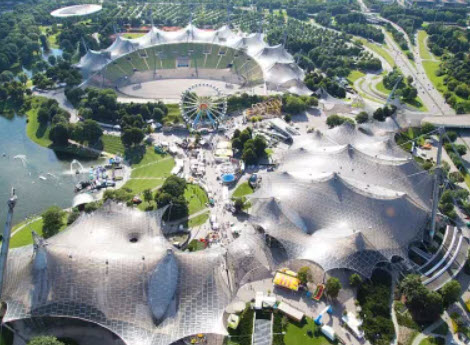
Some of the prominent buildings include Munich OlympiaPark, The Millennium Dome London and Ashford Designer Outlet UK.
Details in Suspended Tension Membrane Covering Systems
1. Membrane Material Selection
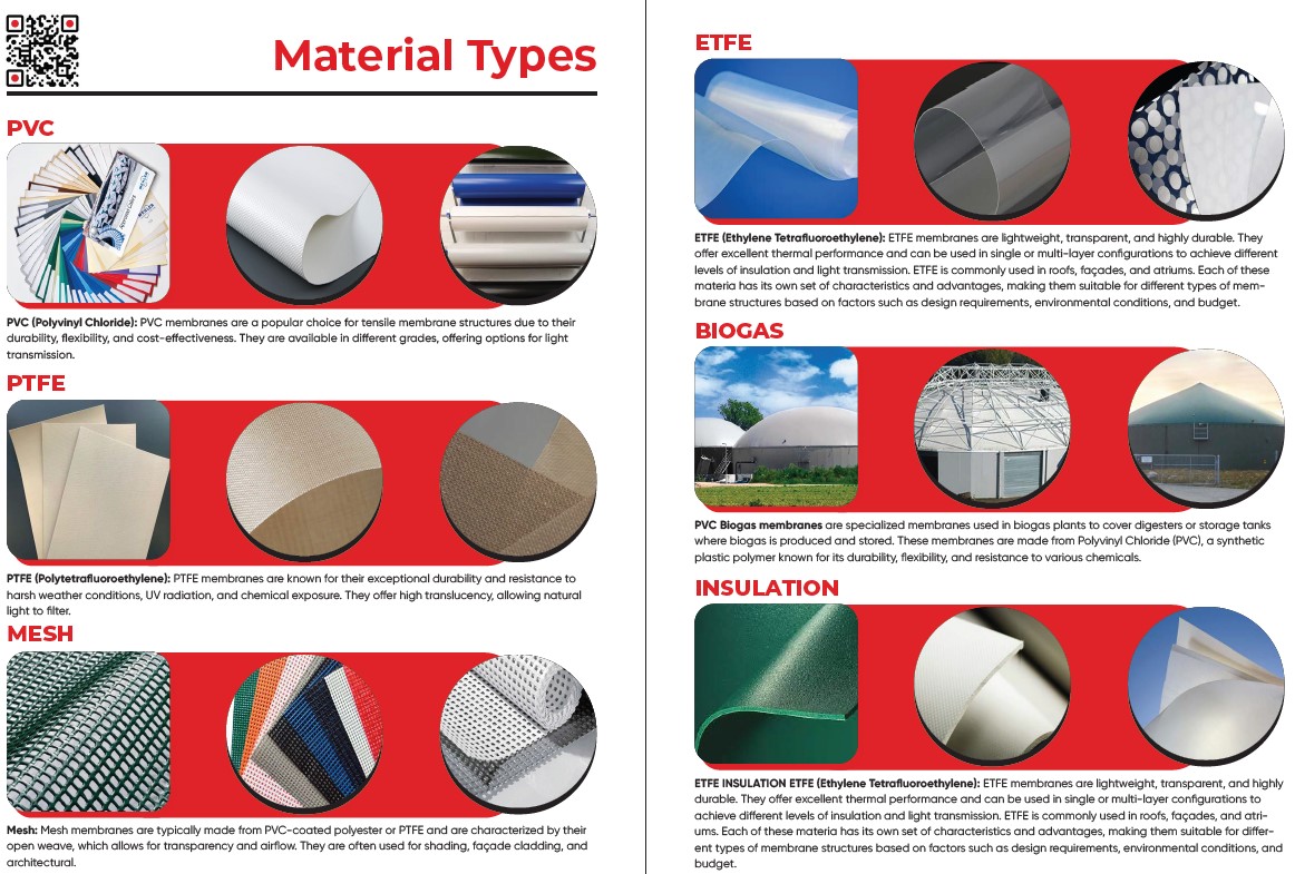
– Material Type: PTFE coated fiberglass, PVC coated polyester fabric or ETFE film. Factors such as the intended use of the building, aesthetic expectations, climatic conditions, cost and fire resistance are taken into account in material selection.
– Light Transmittance: The light transmittance of the material is determined according to the natural light requirements of the project. If an open and bright interior is desired, materials with high light transmittance are preferred.
– Color and Coating: Color and surface coating properties are selected for aesthetic appearance, energy efficiency and temperature control. A reflective coating can reduce solar heat.
2. Structural Design and Analysis
– Static Analysis: Stress analysis is performed to determine the behavior of the membrane under wind, snow and other external loads. This analysis determines where and how much the membrane should be stretched.
– Form Finding Process: The geometry and shape of the membrane is optimized according to the tensile forces. Using computer-aided design software and form-finding simulations, the most suitable form in terms of aesthetics, stability and functionality is obtained.
3. Carrier System and Connection Details
– Main Carrier System: Main supporting structures made of materials such as steel, aluminum or wood are designed to support the membrane structure. The size and placement of these structures are optimized so that the membrane can safely carry its loads.
– Connection Details: How the membranes will be attached to the structure is determined. Connection details such as clamping systems, ropes and tensioning elements, knots are designed. These details ensure that the structure is safe and long-lasting.
– Cable and Rod Tensioning Elements: Steel cables or rods provide tensioning force by stretching the membrane to the support structure. Cable diameters, rod sizes and arrangement of tensioning elements are determined according to structural analysis.
4. Membrane Connection Points and Node Details
– Node Points: The nodes where the membrane is connected to the tension cables or support structures are designed with special fasteners. The correct design of these points ensures that the membrane is resistant to tensile forces.
– Membrane Clamping Details: The edges of the membrane are clamped to steel or aluminum profiles. These clamping details ensure that the membrane is properly stretched and resistant to external influences such as wind.
5. Rainwater Management and Sealing Details
– Rainwater Descent Details: If desired, rainwater downpipes and drainage systems can be designed to direct rainwater in a controlled manner. These systems ensure that water is directed away from the membrane surface and safely discharged from the structure.
– Sealing Details: Sealing details of the membrane cover and joints should be designed to provide watertightness. Sealing materials and fasteners should be carefully selected to prevent water leakage.
– Creek and Existing Building Junction Details: When suspended tension membrane systems are combined with existing buildings, stream details and junctions can be designed to ensure proper drainage of water. These junction details ensure that water is safely directed and discharged between the membrane and the building.
6. Assembly and Installation Details
– Assembly Planning: Detailed planning is required to ensure that the installation process is successful. This planning includes the assembly of the support structures, the tensioning of the membrane and the final connections.
– Installation Process: During installation, the necessary equipment and techniques are used to ensure that the membrane is tensioned correctly.
Creating Details and Decision Making Process
1. Identification of Project Requirements
– The intended use of the building, climatic conditions, aesthetic preferences, budget, local regulations and other requirements are the determining factors in the creation of the details. The architect, engineer and client work together to clarify the project objectives.
2. Structural and Material Analysis
– The architectural and structural design of the structure, the types and properties of materials to be used are determined. Structural analysis determines which stresses and load conditions the membrane will be subjected to. According to these analyses, material selection and tension details are optimized.
3. Digital Simulation and Modeling
– Digital models of the structure are created using computer-aided design and analysis software such as RFEM. These models simulate and optimize how the membrane will respond to tensile forces. The simulation results determine the final design of the details.
4. Prototype and Tests
– If necessary, a small-scale prototype or test model of the structure is prepared to test its structural integrity, tension forces and other factors. The test results verify the accuracy and conformity of the details.
5. Manufacturing and Assembly Planning
– Once the final details have been determined, the manufacturing and assembly processes are planned. This stage ensures that all components are manufactured and assembled correctly. In addition, the equipment, cranes and materials required for assembly operations on site are planned.
Conclusion
Details in suspended tension membrane cover systems are critical to the aesthetics, functionality, safety and durability of the structure. Elements such as rainwater downspouts, sealing, stream and existing building junction details can be designed to improve the performance of the structure. These details should be carefully constructed based on project requirements and structural analysis. Correct material selection, design of stress and connection details ensure successful installation and long life of the structure.